HELI-ROTOR
Principle of Operation
Compression or expansion in the Heli Rotor is accomplished by changing the
volume of a trapped charge as the gas passes through the machine. The direction
of flow is both axial and circumferential. Operation, perhaps, can best be
explained by describing a compression cycle.
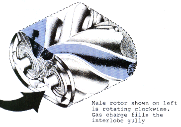
 In the Heli Rotor,
the charge to be compressed is trapped in the gullies between the rotor lobes.
Each rotor is sealed by close fit with the housing, both at the fore and
aft ends and circumferentially. Similarly, the fit between the rotors seals
the gullies at the mesh points.
 Intake and
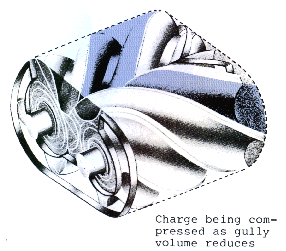
compression occur essentially concurrently. The charge is compressed as the
rotors mesh, moving the seal point toward the discharge port. Shortly after
interlobe sealing occurs, the fore ends of the gullies are again exposed
to the inlet port. Further rotation continues compression while at the same
time the unmeshing portion of each gully gradually fills. Just prior to sealing
at the inlet, the gullies are open for their entire length from intake end
to the seal at the rear housing. Since the charge is admitted gradually over
a large portion of the rotation, inlet losses are low.
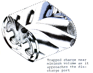
 In compressing
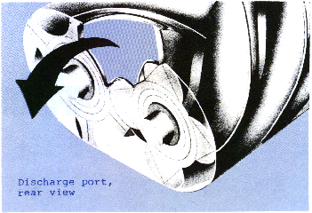
the charge, the trapped gas is reduced in volume as the meshing moves the
interlobe seal axially and rotation carries the charge radially toward the
discharge point.The point at which the moving seal reaches the outlet port
determines the design compression ratio. Intermeshing of the rotors creates,
in effect, a series of interlobe volumes. Trapped volume is reduced while
air is being moved toward the discharge. While the meshing point of a pair
of lobes is moving axially, the next charge is being drawn into the unmeshed
portion. Performance and efficiency of the Heli-Rotor remains high even when
it is operated at flows and pressures far from its specified design points.

To see more information on any of these, select from the table below
Copyright ©
Fred Y. Robinson 1998, All Rights
Reserved
 In the Heli Rotor,
the charge to be compressed is trapped in the gullies between the rotor lobes.
Each rotor is sealed by close fit with the housing, both at the fore and
aft ends and circumferentially. Similarly, the fit between the rotors seals
the gullies at the mesh points.
 Intake and
compression occur essentially concurrently. The charge is compressed as the
rotors mesh, moving the seal point toward the discharge port. Shortly after
interlobe sealing occurs, the fore ends of the gullies are again exposed
to the inlet port. Further rotation continues compression while at the same
time the unmeshing portion of each gully gradually fills. Just prior to sealing
at the inlet, the gullies are open for their entire length from intake end
to the seal at the rear housing. Since the charge is admitted gradually over
a large portion of the rotation, inlet losses are low.
 In compressing
the charge, the trapped gas is reduced in volume as the meshing moves the
interlobe seal axially and rotation carries the charge radially toward the
discharge point.The point at which the moving seal reaches the outlet port
determines the design compression ratio. Intermeshing of the rotors creates,
in effect, a series of interlobe volumes. Trapped volume is reduced while
air is being moved toward the discharge. While the meshing point of a pair
of lobes is moving axially, the next charge is being drawn into the unmeshed
portion. Performance and efficiency of the Heli-Rotor remains high even when
it is operated at flows and pressures far from its specified design points.
